


 |
| Demonstration model of a direct-methanol fuel cell. The actual fuel cell stack is the layered cube shape in the center of the image |
A fuel cell is an electrochemical cell that converts a source fuel into an electric current. It generates electricity inside a cell through reactions between a fuel and an oxidant, triggered in the presence of an electrolyte.
The reactants flow into the cell, and the reaction products flow out of it, while the electrolyte remains within it. Fuel cells can operate continuously as long as the necessary reactant and oxidant flows are maintained.
Fuel cells are different from conventional electrochemical cell batteries in that they consume reactant from an external source, which must be replenished – a thermodynamically open system. By contrast, batteries store electrical energy chemically and hence represent a thermodynamically closed system.
Many combinations of fuels and oxidants are possible. A hydrogen fuel cell uses hydrogen as its fuel and oxygen (usually from air) as its oxidant. Other fuels include hydrocarbons and alcohols. Other oxidants include chlorine and chlorine dioxide.
Design
Fuel cells come in many varieties; however, they all work in the same general manner. They are made up of three segments which are sandwiched together: the anode, the electrolyte, and the cathode. Two chemical reactions occur at the interfaces of the three different segments. The net result of the two reactions is that fuel is consumed, water or carbon dioxide is created, and an electric current is created, which can be used to power electrical devices, normally referred to as the load.
At the anode a catalyst oxidizes the fuel, usually hydrogen, turning the fuel into a positively charged ion and a negatively charged electron. The electrolyte is a substance specifically designed so ions can pass through it, but the electrons cannot. The freed electrons travel through a wire creating the electric current. The ions travel through the electrolyte to the cathode. Once reaching the cathode, the ions are reunited with the electrons and the two react with a third chemical, usually oxygen, to create water or carbon dioxide.
The most important design features in a fuel cell are:
- The electrolyte substance. The electrolyte substance usually defines the type of fuel cell.
- The fuel that is used. The most common fuel is hydrogen.
- The anode catalyst, which breaks down the fuel into electrons and ions. The anode catalyst is usually made up of very fine platinum powder.
- The cathode catalyst, which turns the ions into the waste chemicals like water or carbon dioxide. The cathode catalyst is often made up of nickel.
 |
| A block diagram of a fuel cell |
A typical fuel cell produces a voltage from 0.6 V to 0.7 V at full rated load. Voltage decreases as current increases, due to several factors:
- Activation loss
- Ohmic loss (voltage drop due to resistance of the cell components and interconnects)
- Mass transport loss (depletion of reactants at catalyst sites under high loads, causing rapid loss of voltage).
To deliver the desired amount of energy, the fuel cells can be combined in series and parallel circuits, where series yields higher voltage, and parallel allows a higher current to be supplied. Such a design is called a fuel cell stack. The cell surface area can be increased, to allow stronger current from each cell.
Proton exchange fuel cells
 |
| Construction of a high temperature PEMFC: Bipolar plate as electrode with in-milled gas channel structure, fabricated from conductive plastics (enhanced with carbon nanotubes for more conductivity); Porous carbon papers; reactive layer, usually on the polymer membrane applied; polymer membrane. |
 |
| Condensation of water produced by a PEMFC on the air channel wall. The gold wire around the cell ensures the collection of electric current. |
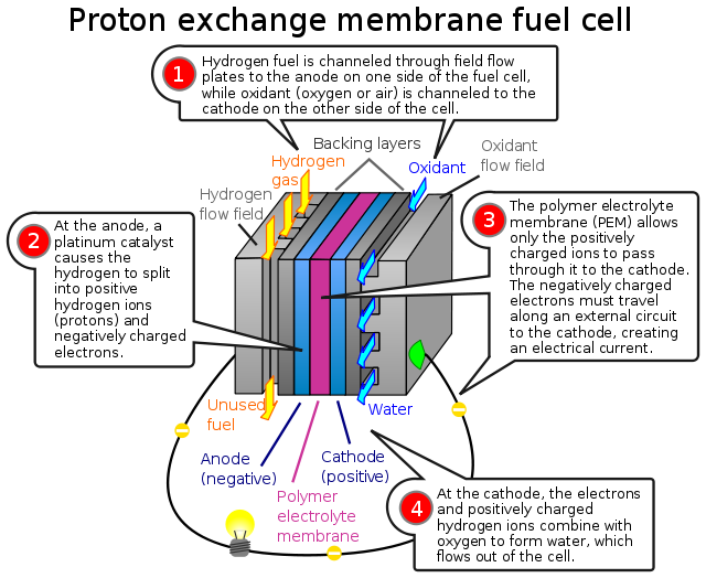
In the archetypal hydrogen–oxygen proton exchange membrane fuel cell (PEMFC) design, a proton-conducting polymer membrane, (the electrolyte), separates the anode and cathode sides. This was called a "solid polymer electrolyte fuel cell" (SPEFC) in the early 1970s, before the proton exchange mechanism was well-understood. (Notice that "polymer electrolyte membrane" and "proton exchange mechanism" result in the same acronym.)
On the anode side, hydrogen diffuses to the anode catalyst where it later dissociates into protons and electrons. These protons often react with oxidants causing them to become what is commonly referred to as multi-facilitated proton membranes. The protons are conducted through the membrane to the cathode, but the electrons are forced to travel in an external circuit (supplying power) because the membrane is electrically insulating. On the cathode catalyst, oxygen molecules react with the electrons (which have traveled through the external circuit) and protons to form water — in this example, the only waste product, either liquid or vapor.
In addition to this pure hydrogen type, there are hydrocarbon fuels for fuel cells, including diesel, methanol (see: direct-methanol fuel cells and indirect methanol fuel cells) and chemical hydrides. The waste products with these types of fuel are carbon dioxide and water.
The materials used in fuel cells differ by type. In a typical membrane electrode assembly (MEA), the electrode–bipolar plates are usually made of metal, nickel or carbon nanotubes, and are coated with a catalyst (like platinum, nano iron powders or palladium) for higher efficiency. Carbon paper separates them from the electrolyte. The electrolyte could be ceramic or a membrane.
Proton exchange membrane fuel cell design issues
- The production costs of the PEM (proton exchange membrane). The Nafion membrane currently costs $566/m². In 2005 Ballard Power Systems announced that its fuel cells will use Solupor, a porous polyethylene film patented by DSM.
- Water and air management (in PEMFCs). In this type of fuel cell, the membrane must be hydrated, requiring water to be evaporated at precisely the same rate that it is produced. If water is evaporated too quickly, the membrane dries, resistance across it increases, and eventually it will crack, creating a gas "short circuit" where hydrogen and oxygen combine directly, generating heat that will damage the fuel cell. If the water is evaporated too slowly, the electrodes will flood, preventing the reactants from reaching the catalyst and stopping the reaction. Methods to manage water in cells are being developed like electroosmotic pumps focusing on flow control. Just as in a combustion engine, a steady ratio between the reactant and oxygen is necessary to keep the fuel cell operating efficiently.
- Temperature management. The same temperature must be maintained throughout the cell in order to prevent destruction of the cell through thermal loading. This is particularly challenging as the 2H2 + O2 -> 2H2O reaction is highly exothermic, so a large quantity of heat is generated within the fuel cell.
- Durability, service life, and special requirements for some type of cells. Stationary fuel cell applications typically require more than 40,000 hours of reliable operation at a temperature of -35 °C to 40 °C (-31 °F to 104 °F), while automotive fuel cells require a 5,000 hour lifespan (the equivalent of 150,000 miles) under extreme temperatures. Current service life is 7,300 hours under cycling conditions. Automotive engines must also be able to start reliably at -30 °C (-22 °F) and have a high power to volume ratio (typically 2.5 kW per liter).
- Limited carbon monoxide tolerance of some (non-PEDOT) cathodes.
- SOFC
- A solid oxide fuel cell (SOFC) is extremely advantageous “because of a possibility of using a wide variety of fuel”. Unlike most other fuel cells which only use hydrogen, SOFCs can run on hydrogen, butane, methanol, and other petroleum products. The different fuels each have their own chemistry. For SOFC methanol fuel cells, on the anode side, a catalyst breaks methanol and water down to form carbon dioxide, hydrogen ions, and free electrons. The hydrogen ions meet oxide ions that have been created on the cathode side and passed across the electrolyte to the anode side, where they react to create water. A load connected externally between the anode and cathode completes the electrical circuit. Below are the chemical equations for the reaction:
- Anode Reaction: CH3OH + H2O + 3O= → CO2 + 3H2O + 6e-
- Cathode Reaction: 3/2 O2 + 6e- → 3O=
- Overall Reaction: CH3OH + 3/2 O2 → CO2 + 2H2O + electrical energy
- At the anode SOFCs can use nickel or other catalysts to break apart the methanol and create hydrogen ions and carbon monoxide. A solid called yttria stabilized zirconia (YSZ) is used as the electrolyte. Like all fuel cell electrolytes YSZ is conductive to certain ions, in this case the oxide ion (O=) allowing passage from the cathode to anode, but is non-conductive to electrons. YSZ is a durable solid and is advantageous in large industrial systems. Although YSZ is a good ion conductor, it only works at very high temperatures. The standard operating temperature is about 950oC. Running the fuel cell at such a high temperature easily breaks down the methane and oxygen into ions. A major disadvantage of the SOFC, as a result of the high heat, is that it “places considerable constraints on the materials which can be used for interconnections”. Another disadvantage of running the cell at such a high temperature is that other unwanted reactions may occur inside the fuel cell. It is common for carbon dust, graphite, to build up on the anode, preventing the fuel from reaching the catalyst. Much research is currently being done to find alternatives to YSZ that will carry ions at a lower temperature.
- MCFC
- Molten carbonate fuel cells (MCFCs) operate in a similar manner, except the electrolyte consists of liquid (molten) carbonate, which is a negative ion and an oxidizing agent. Because the electrolyte loses carbonate in the oxidation reaction, the carbonate must be replenished through some means. This is often performed by recirculating the carbon dioxide from the oxidation products into the cathode where it reacts with the incoming air and reforms carbonate. Unlike proton exchange fuel cells, the catalysts in SOFCs and MCFCs are not poisoned by carbon monoxide, due to much higher operating temperatures. Because the oxidation reaction occurs in the anode, direct utilization of the carbon monoxide is possible. Also, steam produced by the oxidation reaction can shift carbon monoxide and steam reform hydrocarbon fuels inside the anode. These reactions can use the same catalysts used for the electrochemical reaction, eliminating the need for an external fuel reformer. MCFC can be used for reducing the CO2 emission from coal fired power plants as well as gas turbine power plants.
- The principle of the fuel cell was discovered by German scientist Christian Friedrich Schönbein in 1838 and published in one of the scientific magazines of the time. Based on this work, the first fuel cell was demonstrated by Welsh scientist and barrister Sir William Robert Grove in the February 1839 edition of the Philosophical Magazine and Journal of Science and later sketched, in 1842, in the same journal. The fuel cell he made used similar materials to today's phosphoric-acid fuel cell.
 |
| Sketch of William Grove's 1839 fuel cell |
 |
| Configuration of components in a fuel cell car. |


Hi buddy....
ReplyDeleteThis is really informative post. I got the fuel cell information. Thanks for sharing your views.
Machining Ultem